
 Accessories
 Calculus with bits and bytes – Part 2: Touch Gauges as 360° circular sliders Leave a comment
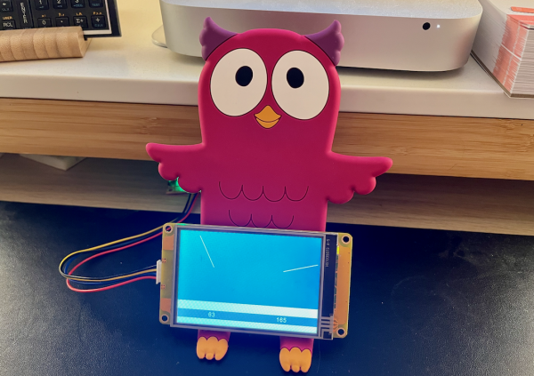
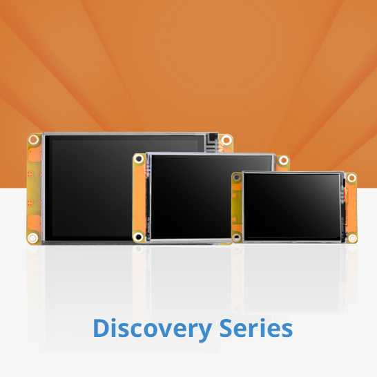
As I announced last week, it is perfectly possible to make a Gauge component touch sensitive and having the needle follow your Finger! And that only with a handful of code lines! And, if needed, even multiple times on the same page without an additional line of code, because the event handling is concentrated in single TouchCap and Timer components for all Gauges. After doing all the heavy theory last Sunday, we realize a proof of concept, today, with two gauges transformed into circular sliders with values from 0 to 360 on a simple and small HMI of the Discovery series. I must admit, the Gauge component there isn’t a beauty. Thus, next time, we’ll switch over to the Intelligent series which gives us a lot more opportunities to realize beautiful and useful controls!
Before you continue reading, please make sure that you read and understood all the theory which is used here to determine the sign of a number, to calculate the absolute value of a number, and how to approximate the atan() function to map values from 0 to 1 (represented as 0 to 256 for more precision) into angles from 0° to 45° in last week’s blog!
Tracking a continuous movement
Besides the linear Slider, no other component allows us to handle a Touch Move Event. So, that’s one of the first things which we’ll need to put in place. But we won’t reinvent the wheel. Similar to the slide gestures to change pages which we did here, we will simply start a timer on touch press and stop it at touch release. Everything else will happen at short intervals like 50ms in the timer event code. To hold the latter short, things which need only to be calculated once for each gesture are added to the touch press event to be handled beforehand. In this case, it’s finding the center x and y components of the gauge component which is actually touched, because the system variables tc0 and tc1 give us the actual touch coordinates, but relative to the upper left corner of the screen. But to calculate an angle we need the touch coordinates relative to the component’s center.
So, we have in the TouchCap tc0‘s Touch Press Event:
if(b['&val&'].type==122) // Gauges only
{
  // Calculate the center coordinates:
  Xc.val=b['&val&'].w>>1+b['&val&'].x
  Yc.val=b['&val&'].h>>1+b['&val&'].y
  // Start the timer to handle the moving touch:
  tm0.en=1
}
And in its Touch Release Event:
if(b['&val&'].type==122) // Gauges only
{
  // Stop the timer:
  tm0.en=0
}
The timer tracks your touching and updates the display
As soon as the timer tm0 is enabled, it will track the actual touch coordinates tc0 and tc1 every 50ms and from that calculate the angle and set the gauge’s .val attribute accordingly. Just for fun, I added one line at the end to update also an associated number component which shows the numerical value. As we have seen last week, the mathematics are quite complicated since our approximated atan() function covers only a 45° angle, so, mathematically, we divide the whole circle into 8 sectors and treat them as different cases and with different angle offsets, mainly depending on the signs of the relative touch coordinates which allow us to know in which sector we are currently touching. This requires the storage of intermediate results in variables. Including the two center coordinates, we have 8 numeric variables. Some of them are re-purposed during the calculation and I could have squeezed everything into still less variables, but then, the readability of the code would have suffered too much. In the actual state, the page with the 2 Gauge, 2 Number, 1 TouchCap, 1 Timer, and 6 Variable components occupies just 184 bytes of the 3584 available. So, there remains much headroom (3400 bytes).
Here is the Timer tm0‘s event code:
// Calculate the touch coordinates relative to the center:
Xr.val=tch0-Xc.val
Yr.val=tch1-Yc.val
// Calculate the signs:
Sx.val=Xr.val>>31<<1+1
Sy.val=Yr.val>>31<<1+1
// Replace the coordinates by their absolute values:
Xr.val*=Sx.val
Yr.val*=Sy.val
// Compute the angle using segmentation and approximation:
if(Yr.val>=Xr.val)
{
  quot.val=Xr.val<<8/Yr.val
  Xr.val=90*Sy.val+180 // reuse the Xr variable to store the offset
  Yr.val=-1*Sx.val*Sy.val // reuse the Yr variable for intermediate result sign
}else
{
  quot.val=Yr.val<<8/Xr.val
  Xr.val=-90*Sx.val+270 // reuse the Xr variable to store the offset
  Yr.val=Sx.val*Sy.val // reuse the Yr variable for intermediate result sign
}
atan.val=256-quot.val*4009+2949120*quot.val+8388608>>24 // see last week's blog ;-)
b[tc0.val].val=atan.val*Yr.val+Xr.val%360 // add the sign and offset to the approximation result, normalize
b[tc0.val+1].val=b[tc0.val].val // update the associated number component
And that’s the whole code. With that, you may now place as many pairs of Gauge and Number components on the page and all gauges will be touch sensitive and follow your finger with the needle! It’s just important to take care of the order when placing the components. The ID of the associated number field has always to be the ID of the gauge plus one.
Here is the project file to study and to play around with it: touch_gauge.HMI
We’ll show how all this can be used to create very beautiful and useful new components like potentiometer knobs on the Intelligent Series HMI.
Last, but not least
You have any questions, comments, critics, or suggestions? Just send me an email to thierry (at) itead (dot) cc! 🙂
And, by the way, if you like and you find useful what I write, and you are about to order Nextion stuff with Itead, please do so by clicking THIS REFERRAL LINK! To you, it won’t forcibly make a change for your order but on some products, you may even get a 10% discount using the coupon code THIERRYFRSONOFF. In ever case, it will pay me perhaps the one or the other beer or coffee. And that will motivate me to write still more interesting blogs 😉
Thank you for reading and happy Nextioning!